





Hydropod — Portable Hydroelectric Generator
Portable energy from moving water. I am designing Hydropod’s electrical architecture and schematic/PCB in Altium Designer.
Overview
Problem
- Multi-day trips need power for small electronics.
- Power banks run out; solar depends on sunlight.
Solution
- Portable turbine harvests moving water and charges a battery.
- Designed for overnight use, including shaded or cloudy conditions.
Users & use cases
- Backpackers, campers, paddlers, anglers, and field researchers.
- Replenish phones, GPS, communicators, lights, and cameras beside camp or during river stops.
Theoretical feasibility
A first-principles estimate asks whether a small turbine could accumulate useful energy over an overnight deployment. This is an assumed operating scenario, not measured Hydropod performance.
Model
Cp converts water power to shaft power; ηelec represents losses from the shaft through generation and charging to stored energy.
Assumptions & worked example
D = 0.15 m · v = 1.5 m/s
ρ = 1,000 kg/m³ · Cp = 0.10 · ηelec = 0.70
Constant flow for 8 hours
Power scales with D² and v³ if efficiencies stay fixed. Actual output depends on turbine behavior, generator loading, conversion losses, and battery limits. This is energy before subsequent USB/device-charging losses, not an output rating or guaranteed stored capacity.
Electrical design
Capture moving water, convert it to DC, and store the energy for small-device charging.
- Moving waterEnergy source
- TurbineWater → rotation
- Brushless generator motorEMAX GB4114 · rotation → 3-phase AC
- Full-wave rectifierSix-diode bridge · AC → DC
- Input protection & sensingTVS · fuse · filtering · INA226
- Buck-boost chargerBQ25690 · manages battery charging
- Battery & protection1S Li-ion · stores energy
- USB outputPlanned boost + current limit → USB-A
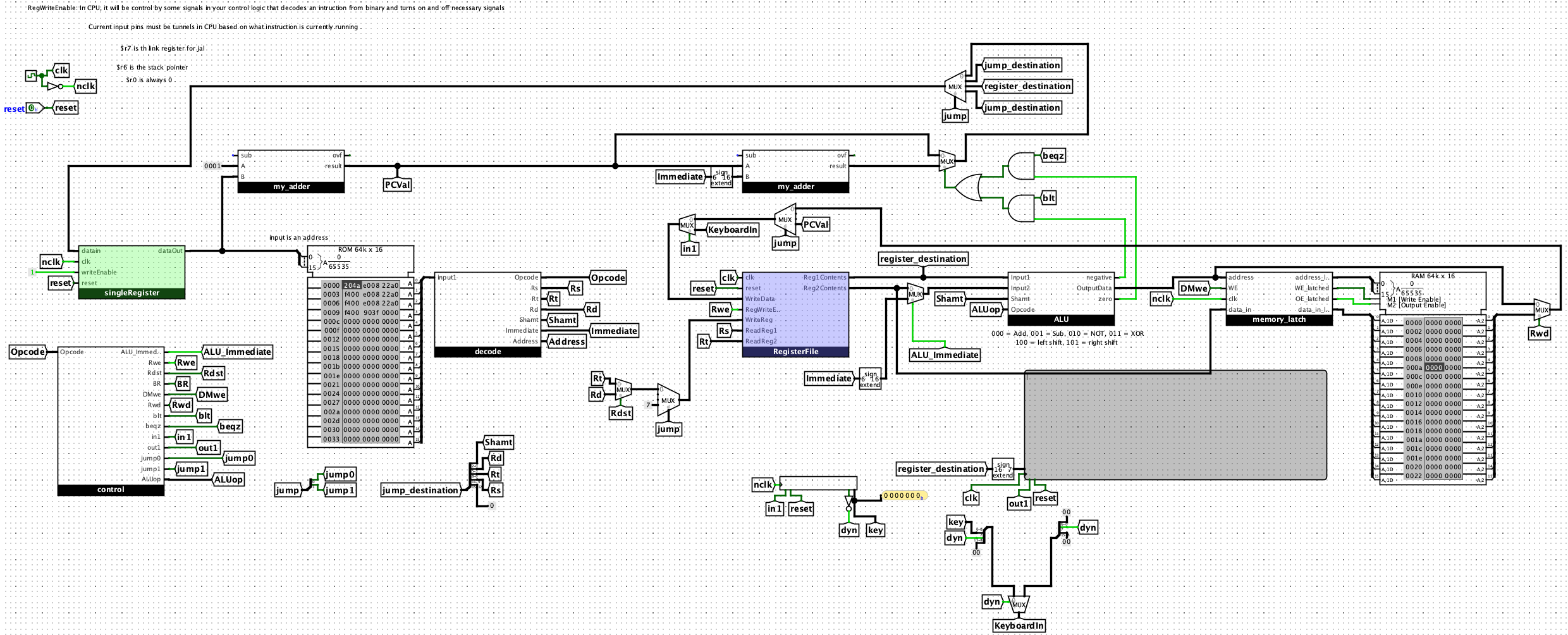
- Completed: Schematic architecture for rectification, input protection and monitoring, battery charging and protection, and MCU sensing/control.
- In progress: Generator braking and USB output circuitry; PCB layout and hardware testing are upcoming.
Input & rectifier
- Capture: J1 receives three-phase AC; six diodes form a full-wave bridge.
- Condition: TVS transient protection, a 3 A fuse, and bulk/high-frequency capacitors condition the rectified rail.
- Measure: INA226 monitors voltage, current, and power over I2C (0x40).
- Considerations: Generator voltage varies with speed and load. Bench characterization must establish operating limits and final component values.
Buck-boost charger
- Manage: TI BQ25690 interfaces the rectified source with the system rail and 1S battery; MCU control uses I2C (0x6A).
- Convert: Buck-boost operation accommodates input above or below battery voltage; an external BATFET is included.
- Considerations: Charging settings, startup behavior, input limits, and supporting values need datasheet review and hardware verification.
Battery & protection
- Store: One off-board Molicel P50B 21700 lithium-ion cell.
- Protect: BQ29700-family protection IC and dual low-side MOSFETs create a hardware protection path independent of firmware.
- Considerations: A compact 1S architecture needs conversion for USB power. Protection and disconnect behavior remain untested.
MCU & sensing
- Control: ATtiny1626-SU, powered from PACK_POS with 100 nF decoupling; shared I2C with 10 kΩ pull-ups.
- Interface: CHG_CE / CHG_STAT / CHG_INT provide charger enable, status, and interrupt signals; 2×3 UPDI supports programming.
- Sense: Charger TS and MCU ADC use separate NTC paths on one cable. A GPIO-switched divider reduces idle current; battery measurement uses the planned internal VDD/10 ADC path.
- Considerations: Thermal protection has a direct charger path. BRAKE_REQ / USB_EN / USB_FLT are reserved; firmware completion is not claimed.
Overvoltage brake · in development
- Planned analog comparator and MOSFET braking path, independent of MCU operation.
- Approximately 26.7 V threshold and 20-second hold are provisional; BRAKE_REQ adds an MCU request.
USB output · in development
- Planned TPS61022 boost → TPS2553 current-limited switch → USB-A.
- USB_EN and USB_FLT reserve control and fault interfaces; output capability remains untested.
Next: complete the remaining circuits, characterize the generator, finalize values and schematic review/ERC, then move to PCB layout and subsystem bring-up.